Disclaimer! I am learning NSX-T, part of my learning is to deploy in my lab - if I contradict the official docs then go with the docs!
Lab Environment#
This NSX-T lab environment is built as a nested lab on my physical hosts. There are four physical ESXi hosts, onto which I will deploy three ESXi VMs, a vCenter Server Appliance, NSX Manager, an NSX Controller cluster, and two NSX Edge Nodes.
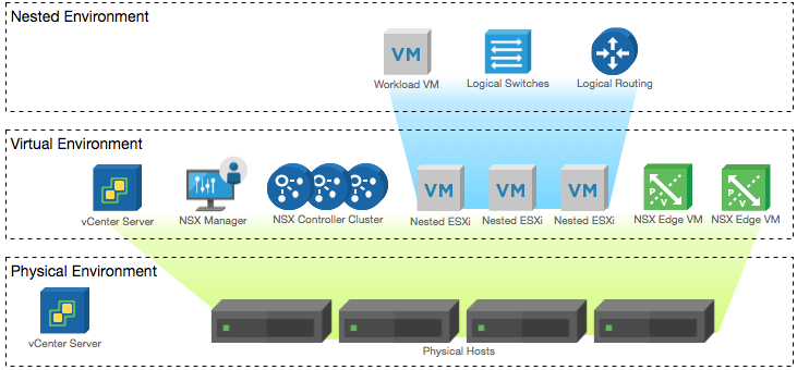
Physical, virtual and nested components of the NSX-T lab
Deployment Plan#
I will follow the deployment plan from the NSX-T 2.0 documentation:
- Install NSX Manager.
- Install NSX Controllers.
- Join NSX Controllers with the management plane.
- Initialize the control cluster to create a master controller.
- Join NSX Controllers into a control cluster.
- Join hypervisor hosts with the management plane.
- Install NSX Edges.
- Join NSX Edges with the management plane.
- Create transport zones and transport nodes.
When this post series is complete, the network topology should be something like this, with two hostswitches configured. The ESXi Hosts will have a Tunnel Endpoint IP address, as will the Edge. The Edge will also have an interface configured for a VLAN uplink.
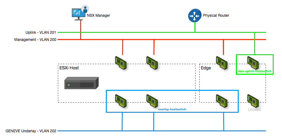
The NSX-T Transport Node network configuration
In this post I will walk through configuring the Transport Zone, Transport Nodes, Edge Cluster and other configuration required to support the deployment.
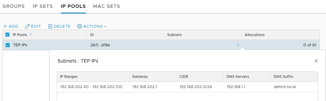
Create an IP Pool for the Tunnel Endpoints (TEPs)#
Both the hosts and edges will require an IP address for the GENEVE tunnel endpoints, so in order to address these without using DHCP or static IPs I have created an IP Pool.
Create an Uplink Profile for VM Edge Nodes#
The NSX-T documentation states:
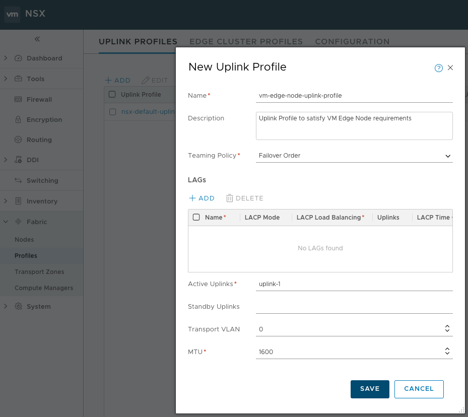
Standby uplinks are not supported with VM/appliance-based NSX Edge. When you install NSX Edge as a virtual appliance, you must create a custom uplink profile rather than use the default uplink profile. For each uplink profile created for a VM-based NSX Edge, the profile must specify only one active uplink and no standby uplink.
Based on this, we need to create a new uplink profile that only includes a single uplink. Enter a name, description, teaming policy (it makes no difference with one uplink!) and enter “uplink-1” in the Active Uplinks. My Edge Nodes will be connected to port groups that already have the VLAN tagging by default, so I don’t need to configure the Transport VLAN setting, but if you were using trunks and VGT you could specify here. MTU is set to 1600 by default.
Creating the Transport Zones#
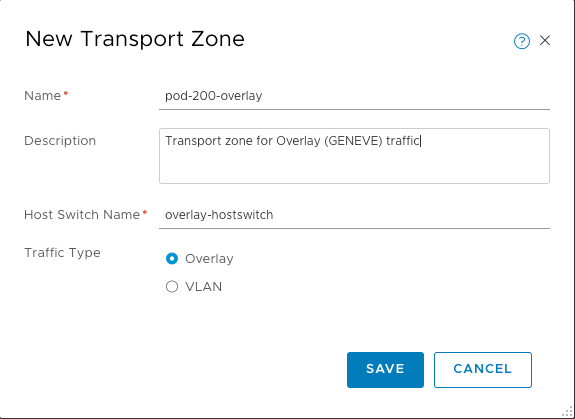
For my lab environment I need two Transport Zones - one for the Overlay traffic, and one for the VLAN uplinks. Transport Zones are created from the Fabric > Transport Zones page and are simple to configure - enter a name, description, host switch name and traffic type.
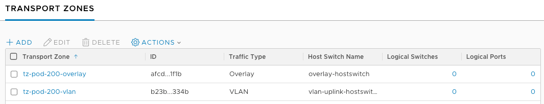
Once created, you can view the two Transport Zones
Creating Host Transport Nodes#
A Transport Node participates in the GENEVE overlay network as well as the VLAN networking - however for my lab configuration the Host Transport Nodes will actually only participate in overlay.
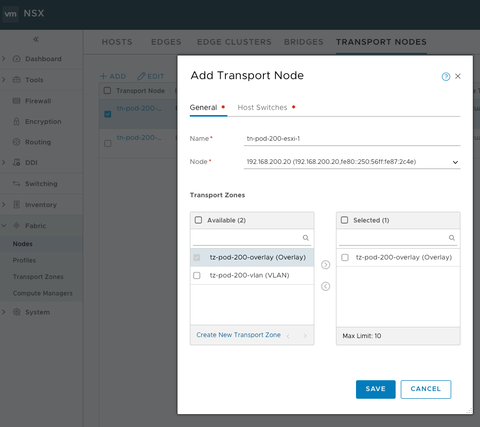
Adding a Transport Node manually (as opposed to doing it via the Compute Manager) is configured from the Fabric > Nodes > Transport Nodes page.
Add the Transport Node and configure a name, select the host to use and the Overlay Transport Zone configured before.
In the Host Switches tab select the Overlay hostswitch, the default NSX Uplink Profile (this defines an active/standby physical NIC configuration), use the TEP IPs pool for IP assignment and then configure the two physical NICs that are dedicated to the Overlay network.
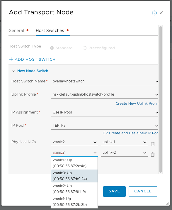
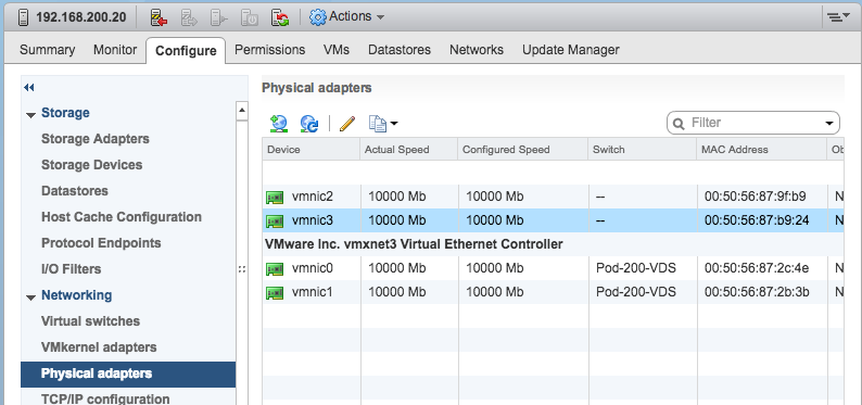
If you’re not sure which vmnic to select, check the MAC address against the Physical adapters in the Host’s configuration.
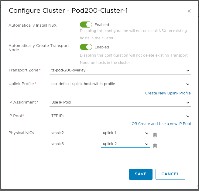
The same Transport Node configuration from the Configure Cluster wizard would look like this:
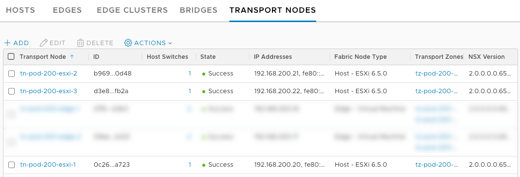
The Host Transport Nodes are now visible from the Transport Nodes page.
Creating Edge Transport Nodes#
A Transport Node participates in the GENEVE overlay network as well as the VLAN uplinks and provides transport between the two. The previously configured VM Edge Nodes will be configured as Edge Transport Nodes, using the Uplink Profile and Transport Zones configured above.
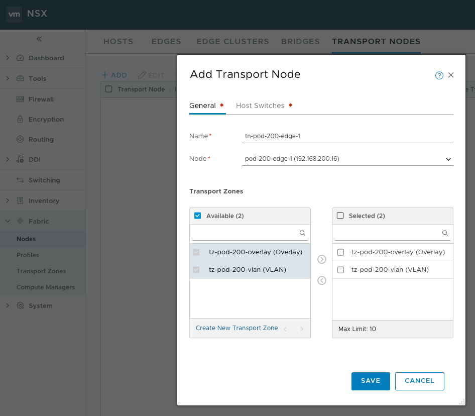
Add a Transport Node from the Fabric > Nodes > Transport Nodes page. Define the Transport Node name, the Node (Edge) that the Transport Node should be configured for, then select at least two Transport Zones (one Overlay and one or more VLAN).
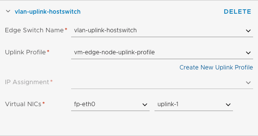
On the Host Switches tab, configure the VLAN Uplink host switch with the Uplink Profile configured earlier. Note that no IP address is required - this is because there is no tunnel endpoint on this interface - we are just passing VLAN traffic. From the Virtual NICs drop down, select the Virtual NIC that matches the MAC address of the VM NIC attached to the uplink port group (e.g. I am using VLAN 201 for the uplink so I selected the matching MAC address). This Virtual NIC is matched to the “uplink-1” active NIC defined in the Uplink Profile.
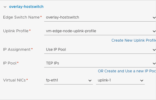
Click ADD HOST SWITCH and configure the Overlay host switch, selecting the same Uplink Profile but this time using Use IP Pool for the IP assignment and selecting the TEP IPs pool. Again, match the correct Virtual NIC with the MAC of the VM NIC attached to the overlay port group. Uplink-1 is selected again because this is the only one defined in the Uplink Profile.
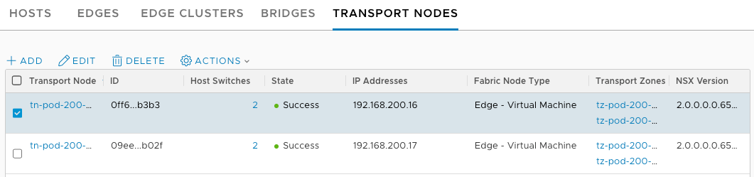
I configured both Edge Transport Nodes
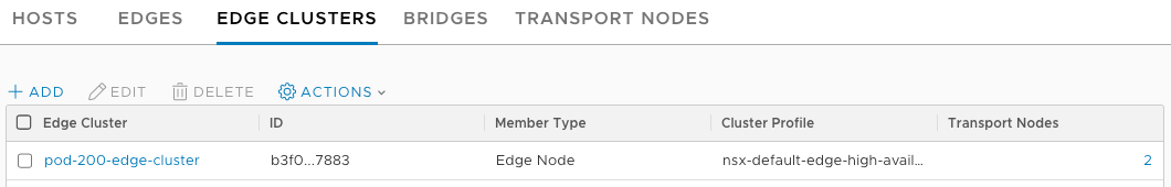
Creating an Edge Cluster#
An Edge Cluster provides availability for the tier-0 router and tier-1 router with stateful services. Even a single Edge Transport Node needs to be part of a cluster to be useful.
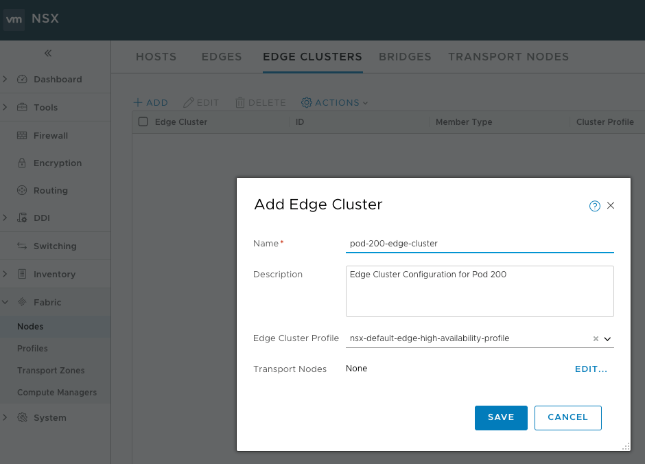
The Edge Cluster is configured from the Fabric > Nodes > Edge Clusters page and is defined using a name, description, an Edge Cluster Profile (which configures things like BFD timers for HA) and the Transport Nodes
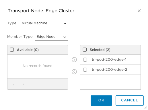
Add both of the Transport nodes (select Type first or none will be visible!) to the Edge cluster, click OK and then Save
The Edge Cluster is now visible on the Edge Clusters page