Disclaimer! I am learning NSX-T, part of my learning is to deploy in my lab - if I contradict the official docs then go with the docs!
Lab Environment#
This NSX-T lab environment is built as a nested lab on my physical hosts. There are four physical ESXi hosts, onto which I will deploy three ESXi VMs, a vCenter Server Appliance, NSX Manager, an NSX Controller cluster, and two NSX Edge Nodes.
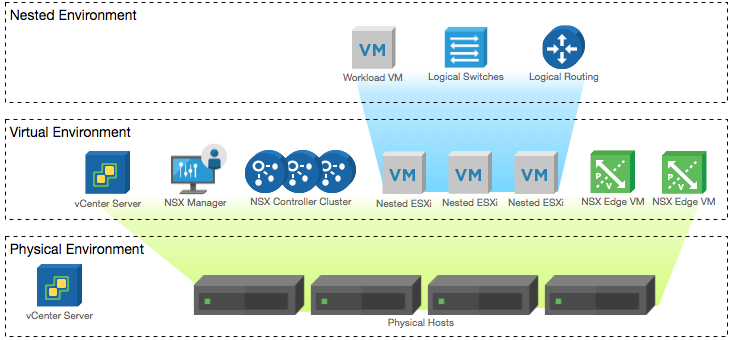
Physical, virtual and nested components of the NSX-T lab
Deployment Plan#
I will follow the deployment plan from the NSX-T 2.0 documentation:
- Install NSX Manager.
- Install NSX Controllers.
- Join NSX Controllers with the management plane.
- Initialize the control cluster to create a master controller.
- Join NSX Controllers into a control cluster.
- Join hypervisor hosts with the management plane.
- Install NSX Edges.
- Join NSX Edges with the management plane.
- Create transport zones and transport nodes.
- Configure Logical Routing and BGP
When this post series is complete, the network topology should be something like this, with two hostswitches configured. The ESXi Hosts will have a Tunnel Endpoint IP address, as will the Edge. The Edge will also have an interface configured for a VLAN uplink.
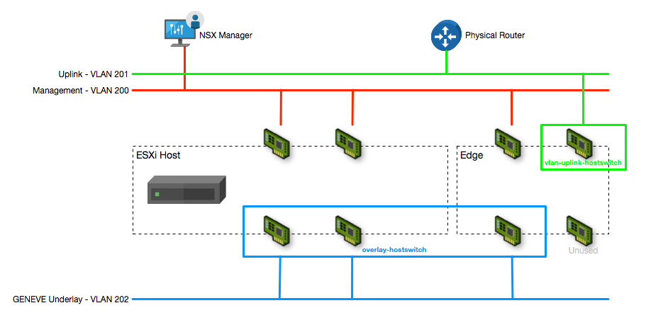
The NSX-T Transport Node network configuration
In this post I will walk through configuring VLAN Logical Switch, Tier-0 Router, Tier-1 Router, Uplink Profiles and BGP dynamic routing to the physical router.
Create VLAN Logical Switch#
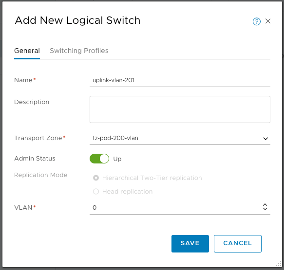
Create a VLAN backed logical switch for the tier-0 router uplink using the Switching > Switches page and enter a name and description. Select the VLAN-backed transport zone created earlier and enter the VLAN number that you want to use to uplink to the physical routers(I am using VLAN 0 because my Edges have NICs connected to a vSphere Port Group that is tagging VLAN 201 - nested can get confusing sometimes!)
Create a Tier-0 Logical Router#
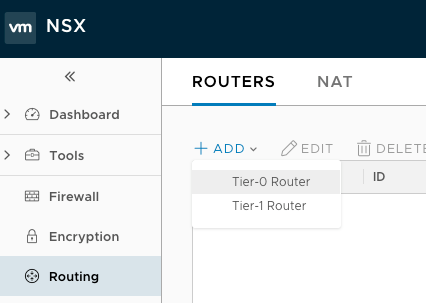
Logical routers are created from the Routing > Routers page, when you click ADD you get the option of a Tier-0 or a Tier-1 router. To start with I am creating the Tier-0 router
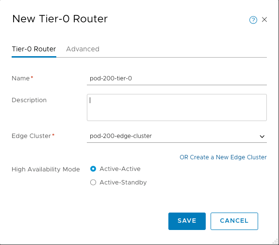
Enter a name and description for the Tier-0 router, then select the Edge Cluster that will host it (this is why you must create an Edge Cluster configuration, even if you only have one Edge Node). Select the High Availability mode:
By default, the active-active mode is used. In the active-active mode, traffic is load balanced across all members. In active-standby mode, all traffic is processed by an elected active member. If the active member fails, a new member is elected to be active.
Click SAVE to complete the Tier-0 Router creation
Create NSX Edge Uplink#
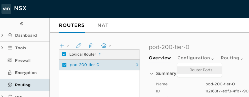
To allow traffic to flow in and out of the NSX environment, I need to connect the Tier-0 Logical Router to a VLAN Logical Switch (created earlier). This is done from the Routing > Routers page by selecting the desired Logical Router, then using the Configuration menu and selecting Router Ports.
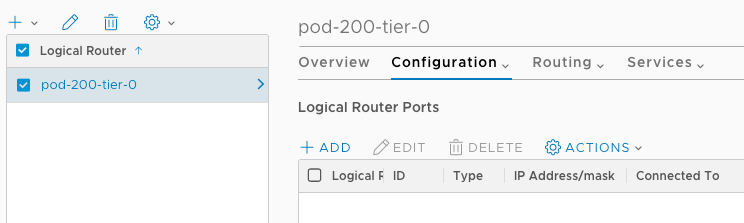
From the Logical Router Ports page, click +ADD
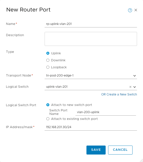
Enter a name and description for the new Router Port. Select the type (uplink here, as I’m creating the uplink to my physical network). Select the first Edge in the Transport Node drop down, then the VLAN backed logical switch created previously. As this is the first switch port on the logical switch, select Attach to a new switch port, then enter a sensible name for the switch port. Finally, enter the IP address and mask for the uplink - this should be in the same subnet as the physical network it’s connecting to.
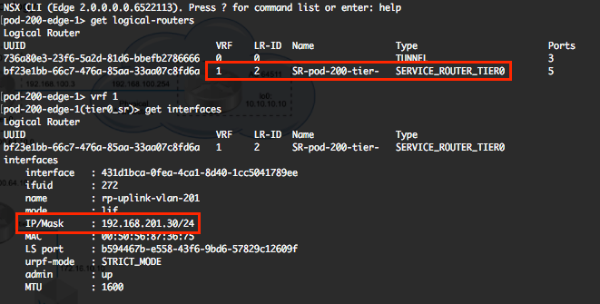
Validate the interface configuration by connecting to the Edge Node via SSH and using “get logical-routers”, identifying the tier-0 router vrf, then “vrf 1”, then get interfaces.
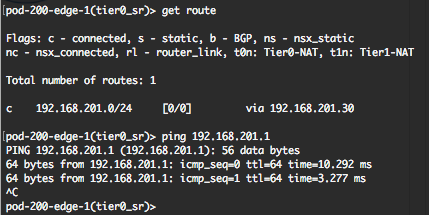
“get route” will show the connected network, and you should be able to ping the gateway to confirm connectivity.
Configure a Tier-1 Logical Router#
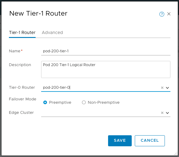
From the Routing > Routers page, add a new Tier-1 router. Configure a name (remember you can have multiple tier-1 routers connected to a tier-0, so you might need to consider that when naming), description and the tier-0 router to uplink to. The failover mode can be configured preemptive or non-preemptive:
Preemptive - If the preferred node fails and recovers, it will preempt its peer and become the active node. The peer will change its state to standby. This is the default option.
Non-preemptive - If the preferred node fails and recovers, it will check if its peer is the active node. If so, the preferred node will not preempt its peer and will be the standby node.
If you’re configuring stateful services (e.g. NAT) then you also need to configure which Edge Cluster the Tier-1 router will be connected to. At this point I don’t want to configure NAT, so I’ll leave it blank for now and come back to it when I configure NAT.
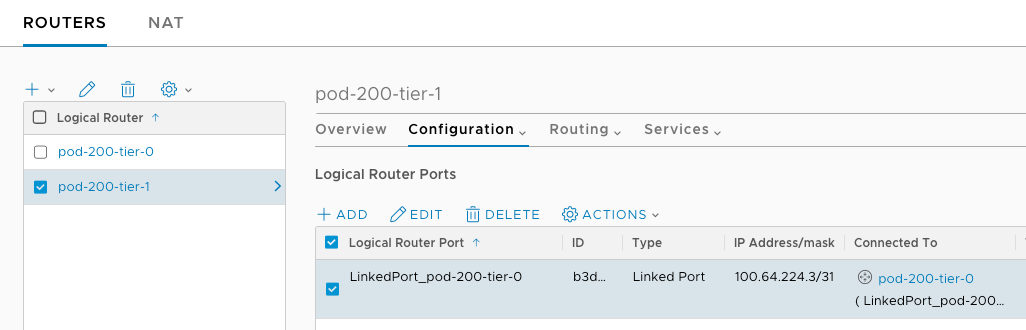
Once created, you can validate the Tier-1 router has been connected to the Tier-0 router by selecting it in the console, then selecting Configuration > Router Ports. A new Linked Port will have been created, auto-addressed, and connected to the Tier-0 router.
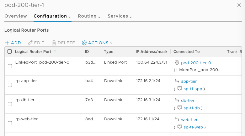
So that we have something to advertise through BGP, I’ve created 3 logical switches and attached them to the Tier-1 router:
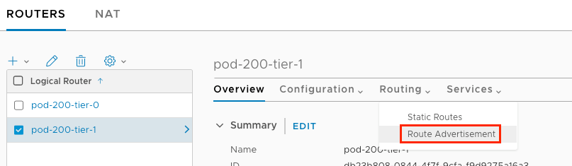
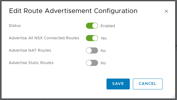
Finally, on the Tier-1 router I need to advertise the connected networks up to the Tier-0 router. Edit the Route Advertisement under the Routing tab on the Tier-1 router configuration.
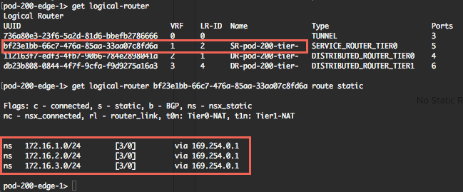
You can validate that the routes are being distributed to the Tier-0 router from the Tier-1 router by SSHing to the Edge Node and running “get logical-router”. Identify the Tier-0 Service Router UUID and run “get logical-router
Configure BGP on the Tier-0 Router#
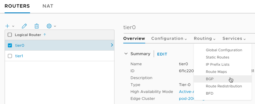
From the Routing > Routers page, select the Tier-0 router and then select BGP from the Routing menu
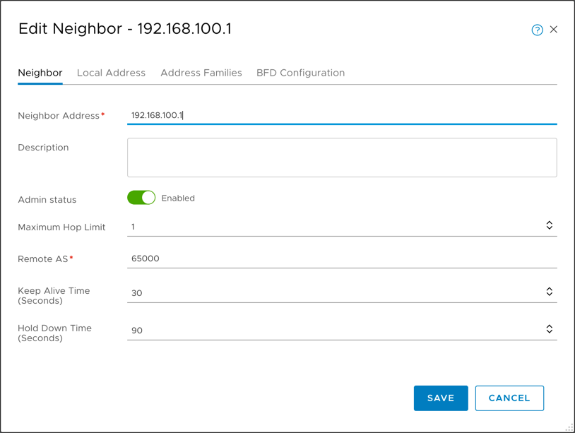
Add a new BGP neighbour and configure to peer with the physical router (which should be on the same subnet as the Tier-0 router).
Note: In my lab I’ve modified the VLAN logical switch uplink on the Edge cluster to sit on the same VLAN as a physical router device, which is on the 192.168.100.0/24 network. The Tier-0 router is now 192.168.100.15.
Enter the Neighbo(u)r IP address, the Remote AS of the physical router, and make sure the Keep Alive and Hold Down times match.
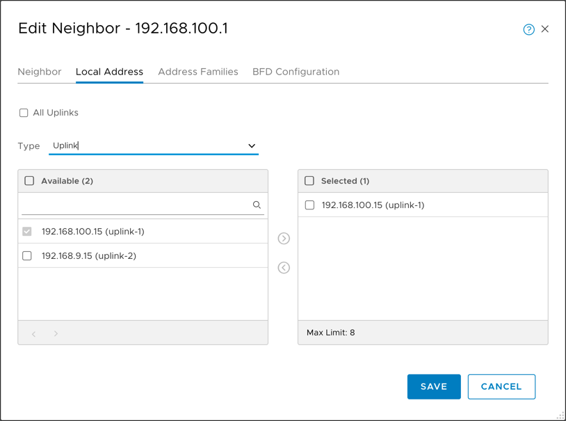
Although not strictly required, it’s also good to specify the local address this peering will communicate on. If, for example, you will configure ECMP at a later point, you will want to configure this. Uncheck the “All Uplinks” box and select the correct Uplink.
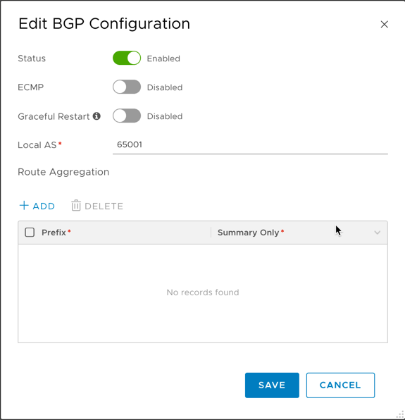
Edit the global BGP Configuration and enable BGP.
We can now validate the BGP neighbour and check that the routes are populated on the physical router.
SSH to the Edge Transport node and use “get logical-router” to list the logical routers. Identify the Tier-0 service router VRF and enter the VRF context using “vrf
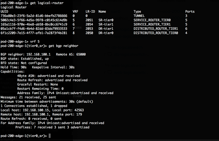
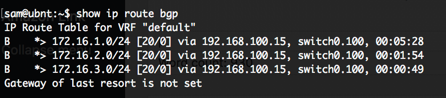
To validate the route tables are updated, use “get route bgp” on the Tier-0 service router VRF, and the equivelant on the physical router. Below you can see the learned BGP routes on my lab EdgeRouter X, which correspond to the networks created on my Tier-1 router.